FFT音律灯
2024-12-05
Update history
| Date | Version | Author | Update content |
|---|---|---|---|
| 2024-12-05 | 1.0.1 | 老怪鸽 | 更新了基本文档 |
本文继承自之前的👉彩灯驱动章节
本文完成的效果:
硬件准备
WS2812矩阵彩灯
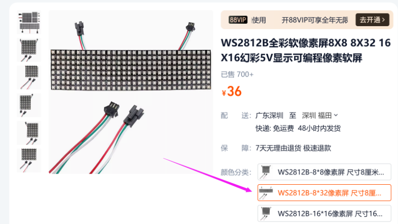
购买地址:WS2812B全彩软像素屏8X8 8X32 16X16幻彩5V显示可编程像素软屏
麦克风模块
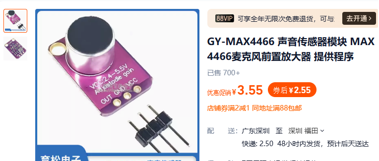
购买地址:GY-MAX4466 声音传感器模块 MAX4466麦克风前置放大器 提供程序
ESP32S3开发板
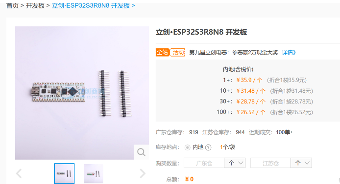
购买地址:立创·ESP32S3R8N8 开发板
工程创建
在VSCode中打开PlatformIO扩展创建名为OscillatingLED的 Espressif ESP32-S3-DevKitM-1 工程。
关于详细图文创建工程的过程请参考👉RTC时钟驱动章节的工程创建小节。
安装驱动库
创建完成之后,打开驱动库下载界面。实现功能的最底层的驱动,需要分别安装三个库:
搜索
Adafruit NeoMatrix,安装来自Adafruit的Adafruit NeoMatrix库。搜索
Adafruit GFX Library,安装来自Adafruit的Adafruit GFX Library库。搜索
arduinoFFT,安装来自Enrique Condes的arduinoFFT库。
将它们都安装到我们的工程当中。
关于详细图文安装驱动库的过程请参考👉RTC时钟驱动章节的安装驱动库小节。
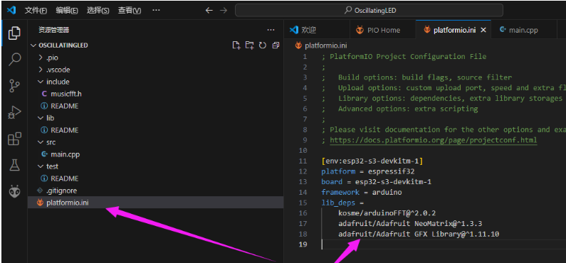
都安装完成之后,打开platformio.ini文件,应该可以看到已经安装上了三个驱动库。
编辑代码
在工程下的include文件夹下新建一个 musicfft.h文件。
接下来往 musicfft.h 文件写入代码:
#include <Adafruit_NeoMatrix.h>
#include <arduinoFFT.h>

#define CHANNEL 1  //音频输入引脚
#define xres 32
#define yres 8


const uint16_t samples = 64; //采样点数,必须为2的整数次幂
const double samplingFrequency = 4000; //Hz, 声音采样频率

unsigned int sampling_period_us;
unsigned long microseconds;
unsigned long lastTime = 0;
unsigned long fallingTime = 0;

double vReal[samples]; //FFT采样输入样本数组
double vImag[samples]; //FFT运算输出数组
int freq_gain2[xres] = {30, 30, 30, 30, 30, 30, 30, 30, 30, 30, 30, 30, 30, 30, 30, 30, 30, 30, 30, 30, 30, 30, 30, 30, 30, 30, 30, 30, 30, 30, 30, 30};
int Intensity[xres] = {}; // initialize Frequency Intensity to zero
int FallingPoint[xres] = {0,0,0,0,0,0,0,0,0,0,0,0,0,0,0,0,0,0,0,0};
int Displacement = 1;          // Create LED Object

//ArduinoFFT FFT = ArduinoFFT(); //创建FFT对象
ArduinoFFT<double> FFT = ArduinoFFT<double>(vReal, vImag, samples, samplingFrequency);


void getSamples(){
  microseconds = micros();
  for(int i = 0; i < samples; i++){
    vReal[i] = analogRead(CHANNEL);
    vImag[i] = 0;
    microseconds += sampling_period_us;
  }
  bool reduce = false;
  if ((millis() - lastTime) > 16) {
    lastTime = millis();
    reduce = true;
  }
  //FFT
  FFT.windowing(vReal, 1, FFT_WIN_TYP_HAMMING, FFT_FORWARD);
  FFT.compute(vReal, vImag, samples, FFT_FORWARD);
  FFT.complexToMagnitude(vReal, vImag, samples);
  //Update Intensity Array
  int t = 16;
  for(int i = t; i < (xres*Displacement)+t; i+=Displacement){
    vReal[i] = constrain(vReal[i], 0 ,3596);            // set max value for input data
    vReal[i] = map(vReal[i], freq_gain2[(i-t)/Displacement], 1548, 0, yres);        // map data to fit our display
    if(reduce){
      Intensity[(i-t)/Displacement] --;                      // Decrease displayed value
    }
    if (vReal[i] > Intensity[(i-t)/Displacement])          // Match displayed value to measured value
      Intensity[(i-t)/Displacement] = vReal[i];
  }
}

void drawYLine(Adafruit_NeoMatrix *matrix, int16_t x, int16_t y, int16_t h, int16_t c){
  for(int i=y;i<y+h;i++){
    matrix->drawPixel(x,7 - i,c);
  }
}

uint16_t hsv2rgb2(Adafruit_NeoMatrix *matrix, uint16_t hue, uint8_t saturation, uint8_t value)
{
    uint8_t red = 0;
    uint8_t green = 0;
    uint8_t blue = 0;
    uint16_t hi = (hue / 60) % 6;
    uint16_t F = 100 * hue / 60 - 100 * hi;
    uint16_t P = value * (100 - saturation) / 100;
    uint16_t Q = value * (10000 - F * saturation) / 10000;
    uint16_t T = value * (10000 - saturation * (100 - F)) / 10000;

    switch (hi)
    {
    case 0:
        red = value;
        green = T;
        blue = P;
        break;
    case 1:
        red = Q;
        green = value;
        blue = P;
        break;
    case 2:
        red = P;
        green = value;
        blue = T;
        break;
    case 3:
        red = P;
        green = Q;
        blue = value;
        break;
    case 4:
        red = T;
        green = P;
        blue = value;
        break;
    case 5:
        red = value;
        green = P;
        blue = Q;
        break;
    default:
        return matrix->Color(255, 0, 0);
    }
    red = red * 255 / 100;
    green = green * 255 / 100;
    blue = blue * 255 / 100;
    return matrix->Color(red, green, blue);
}

void displayUpdate(Adafruit_NeoMatrix *matrix, int displayPattern){
  int color = 0;
  switch(displayPattern){
    case 0:
      for(int i = 0; i < xres; i++){
        drawYLine(matrix,i,yres-Intensity[i],Intensity[i],hsv2rgb2(matrix, color, 80, 80 ));
        drawYLine(matrix,i,0,yres-1-Intensity[i],hsv2rgb2(matrix, color, 80, 80 ));
        color += 360/xres;
      }
      break;
    case 1:
      if ((millis() - fallingTime) > 130) {
        for(int i = 0; i < xres; i++){
          if(FallingPoint[i]>0){
            FallingPoint[i]--;
          }
        }
        fallingTime = millis();
      }
      for(int i = 0; i < xres; i++){
        drawYLine(matrix,i,0,yres-1,matrix->Color(0,0,0));
        if(FallingPoint[i]<Intensity[i]){
          FallingPoint[i] = Intensity[i];
        }
        drawYLine(matrix,i,yres-Intensity[i]+1,Intensity[i]-1,hsv2rgb2(matrix, color, 80, 80 ));
        if(FallingPoint[i]>0){
          matrix->drawPixel(i,yres-FallingPoint[i],matrix->Color(255,255,255));
        }
        color += 360/xres;
      }
      break;
    case 2:
      for(int i = 0; i < xres; i++){
        drawYLine(matrix,i,0,yres,matrix->Color(0,0,0));
        drawYLine(matrix,i,0,Intensity[i]+1,hsv2rgb2(matrix, color, 80, 80 ));
        color += 360/xres;
      }
      break;
  }
}
接下来在 main.cpp中编写以下代码:
#include <Arduino.h>
#include <Adafruit_NeoMatrix.h> //点亮LED矩阵需要的库
#include "musicfft.h" //音乐频谱库

//像素阵列定义
#define kMatrixWidth   32             //宽度
#define kMatrixHeight  8              //高度
#define BRIGHTNESS     10            //默认亮度 0-255
#define BRIGHTNESS_INTERVAL 30        //亮度调节间隔
#define LED_PIN        8              //像素阵列引脚

Adafruit_NeoMatrix *matrix;     //LED矩阵类指针

//像素矩阵初始化
void InitLED_Matrix(void)
{
  //设置像素矩阵的方向以及排列方式
  matrix = new Adafruit_NeoMatrix(32, 8, LED_PIN, NEO_MATRIX_TOP + NEO_MATRIX_LEFT+
    NEO_MATRIX_COLUMNS +  NEO_MATRIX_ZIGZAG,
    NEO_GRB + NEO_KHZ800);
  matrix->setTextWrap(false);       //设置文字是否自动换行
  matrix->clear();                  //清除当前显示内容
  matrix->setBrightness(BRIGHTNESS);//设置亮度
}

void showFFT(void)
{
  //进行采样
  getSamples();
  //更新频谱柱
  displayUpdate(matrix, 2);
}

void setup()
{
  //初始化LED矩阵显示
  InitLED_Matrix();
}

void loop()
{
  matrix->clear();
  showFFT();
  matrix->show();

  delay(50);
}
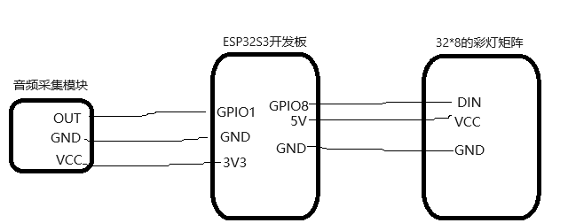
硬件连接
6. 代码验证
代码编写完成之后,将ESP32S3开发板接入电脑下载代码。然后观察彩灯矩阵的现象。
实物显示如下:
使用黑色亚克力面板+白纸格挡光线显示
叠层从上到下是这样的:黑色亚克力面板 -> 白纸 -> LED矩阵
说明:如果你根据代码操作运行不起来,可以下载👉例程看看